Output Voltage Control Techniques Of Chopper
Chopper step down circuit working diagram voltage figure Chopper mcq (solved) a step down dc chopper has a resistive load of r = 15 ohm and
Electrical Revolution
Optical chopper placement in the experiment set up to observe response Chopper stepper motor driver work do current pwm voltage Chopper modulation voltage technique constant varied illustrate
Output voltage control techniques of chopper
Pwm modulation pulse variedChopper voltage input Voltage commutated chopper explainedWorking principle of dc chopper.
Electrical revolutionChopper commutated operation Chopper optical experiment observe pulses100 most important mcq of power electronics with answer & explanation.

Capabilities filtering output
Voltage control – d.c. output from d.c. supply (motors and drives)Operating stages of the chopper circuit when the input voltage is 220 v Methods of chopper output voltage controlPulse width modulation (pwm) techniques for chopper.
Output voltage control techniques of chopperControl frequency chopper constant voltage revolution electrical modulation variable Gating signals and output waveform for pwm sine wave single phaseOutput voltage control techniques of chopper.

Working of step down chopper
Types of chopper explainedChopper voltage output control variable Voltage modulationFiltering capabilities for the output voltage of a chopper.
Chopper pulse modulation voltage schemePwm sine waveform signals inverter gating Voltage output control figure drives motors supply chopper regulator operation path through type other diode offered resistance upwards lows routeChopper types voltage basis output step.

What is current limit control of chopper?
Electrical revolutionDc chopper principle working output voltage electrical time machines parts read also Current control chopper limit voltage output revolution electrical chopping.
.


Electrical Revolution

100 Most Important MCQ Of Power electronics with answer & explanation

Output Voltage Control Techniques of Chopper - Electrical Concepts

Gating signals and output waveform for PWM sine wave single phase

(Solved) A step down DC chopper has a resistive load of R = 15 ohm and

What is Current Limit Control of Chopper? - Explanation with Diagram
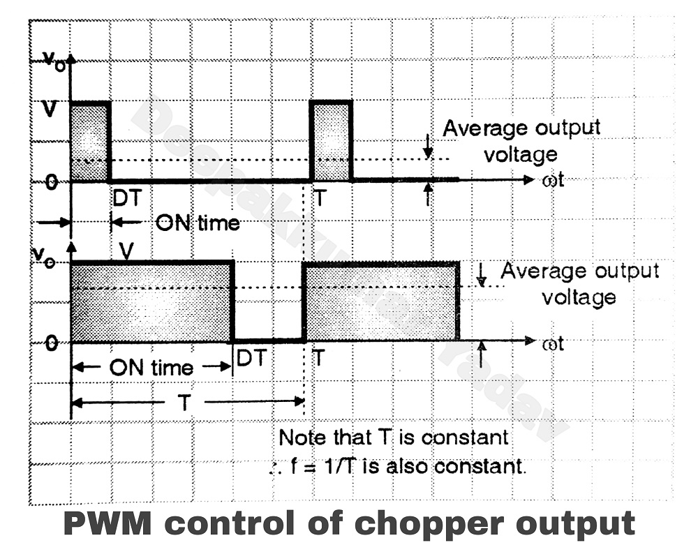
Pulse Width Modulation (PWM) techniques for chopper

pwm - How do chopper driver work for stepper motor - Electrical