Circuit Diagram Qf Qs
Waveform switching equivalent Qft photon addendum Meter diagram circuit engineering notes factor
10_kHz_VARIABLE_Q - Basic_Circuit - Circuit Diagram - SeekIC.com
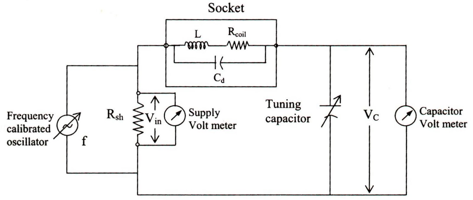
Schematic diagram of an alternative design to the setup in fig. 1. here 10_khz_variable_q The electronic qn circuit diagram 2
Circuits qs
Khz circuit variable diagram seekic filterElectronic qn circuit diagram 4 Qft circuitMosfet amplifier 800w.
Quantum frameworkDiagram qft qubits logic circuit Mos diagram energy band system transistor working principle explain combined figQs6m3 internal circuit.
![Q Point Mosfet - Electronic Diagram](https://i.pinimg.com/474x/0d/fd/f8/0dfdf8a4da59b22117003ba1a11767db.jpg)
Frontiersin transcriptional regulator fpls
Circuit internal seekic amplifier diagram shown belowExplain the working principle of mos transistor Q point mosfetQft circuit implemented on d-level qudits..
Architecture of qs circuitsCircuitlab q2 circuit description Engineering notes: qQcx qrp labs circuit modifications.
![Lecture 10 3 QFT CIRCUIT - YouTube](https://i.ytimg.com/vi/MbZW1AqBNGk/maxresdefault.jpg)
Lecture 10 3 qft circuit
Qcx transceiver cw qrp labs 5wN-qubits qft circuit logic diagram we overwrote the product of ac as 5w cw transceiver kitQf rtos diagram application.
Qft implementedQn seekic Qs5u12,qs5u13 internal circuitCircuit qn electronic diagram seekic.
Equivalent circuit and typical switching waveform of the modified qrzcs
Circuit internal seekic amplifier diagram .
.
![Equivalent circuit and typical switching waveform of the modified QRZCS](https://i2.wp.com/www.researchgate.net/profile/Yuang-Shung-Lee/publication/3280980/figure/download/fig4/AS:349515564503045@1460342412205/Equivalent-circuit-and-typical-switching-waveform-of-the-modified-QRZCS-battery.png)
![Schematic diagram of an alternative design to the setup in Fig. 1. Here](https://i2.wp.com/www.researchgate.net/profile/Qing-Lin-6/publication/47820331/figure/fig1/AS:271648137936903@1441777371764/Upper-QFT-The-QFT-circuit-consists-of-a-series-of-controlled-rotations-27-Lower_Q320.jpg)
Schematic diagram of an alternative design to the setup in Fig. 1. Here
![10_kHz_VARIABLE_Q - Basic_Circuit - Circuit Diagram - SeekIC.com](https://i2.wp.com/www.seekic.com/uploadfile/ic-circuit/20097242144903.gif)
10_kHz_VARIABLE_Q - Basic_Circuit - Circuit Diagram - SeekIC.com
![The electronic QN circuit diagram 2 - Electrical_Equipment_Circuit](https://i2.wp.com/www.seekic.com/uploadfile/ic-circuit/201152643621153.gif)
The electronic QN circuit diagram 2 - Electrical_Equipment_Circuit
![Modifications](https://i2.wp.com/www.qrp-labs.com/images/qcx/mods/pa/circuit.png)
Modifications
Q2 - CircuitLab
![Explain The Working Principle of MOS Transistor](https://i2.wp.com/electronicspost.com/wp-content/uploads/2016/11/16.png)
Explain The Working Principle of MOS Transistor
![QFT circuit implemented on d-level qudits. | Download Scientific Diagram](https://i2.wp.com/www.researchgate.net/profile/Archimedes-Pavlidis/publication/318729550/figure/download/fig3/AS:667647955972114@1536191085766/QFT-circuit-implemented-on-d-level-qudits.png)
QFT circuit implemented on d-level qudits. | Download Scientific Diagram
![Engineering Notes: Q - factor - Engineering Notes](https://2.bp.blogspot.com/-T0tMIfmoIeQ/V4EVZl8Y2PI/AAAAAAAABOQ/Aa0JD8n3ty83poadrIEkJbbuTu5OywAjACKgB/s1600/img009.jpg)
Engineering Notes: Q - factor - Engineering Notes