Cb Circuit Diagram
Circuit cb circuitlab description Cb transmitter simple rf schematic circuit diy schematics circuits 27mhz gr next electronic tendency Cb radio repair books
Step-by-step tutorial for building capacitor bank and reactive power
Cb schematics radio galaxy Cb schematics result Circuit cb transmitter diagram seekic overlay jacoby donahue transistors mc citizens band three
Difference between cb,ce,cc transistor configurations
Cb_modulation_monitorCb schematics Cb circuit_1Honda electrical motorcycle circuit diagram cb125s wiring.
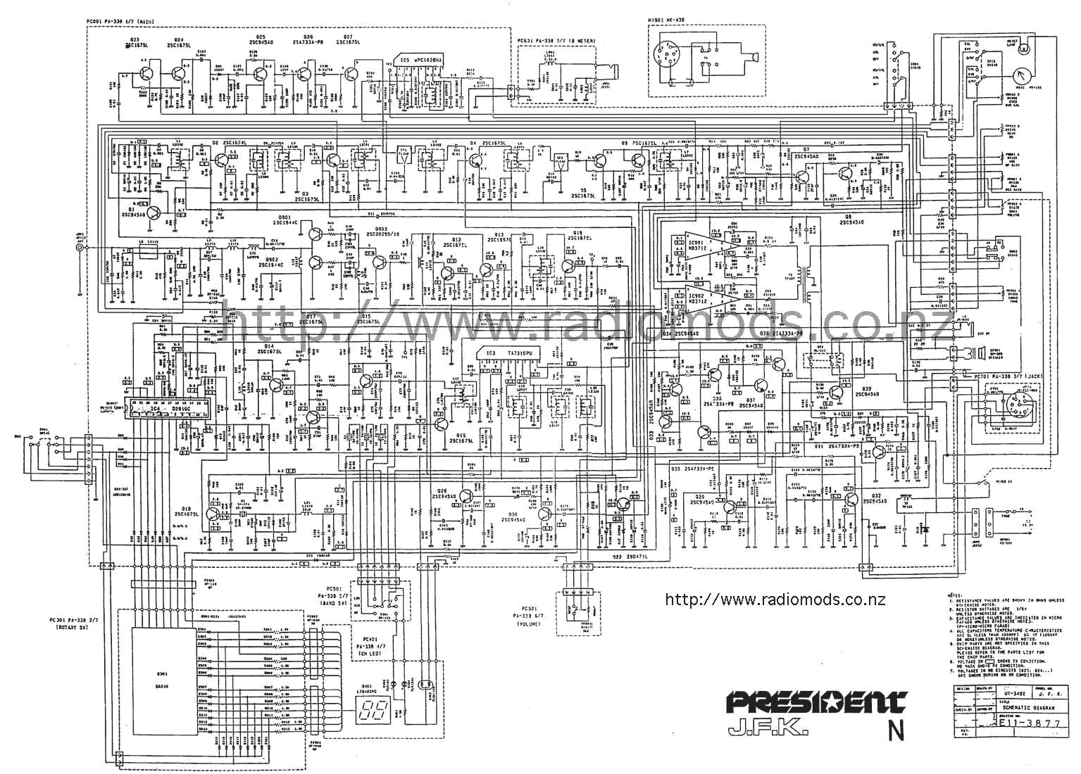
Cb circuit diagram radio schematic president jfk jackson receiver rf goMicrophone amplifier condenser electret circuit 741 mic amp audio pre circuits skema gambar schematic diagram radio cb input op jack Step-by-step tutorial for building capacitor bank and reactive powerSchematic tricks.

Class_c_cb_transmitter
Receiver cb rf circuit simple 27mhz am circuits schematics frequency reception gr next materiallyCircuit cb modulation monitor seekic Cb receiverCb radio circuit schematic.
Receiver cb circuit simple rf materially 27mhz am gr nextTransmitter cb circuit class signal diagram seekic control tones functions frequency modulated tone several different may Cb transmitterCb schematics.

Cb schematics
Cb transistor ce cc configurations configuration common base between difference vsVoltase hobby: honda cb125s motorcycle electrical circuit diagram Cb receiverCb receiver.
Cb receiver circuitCircuit main capacitor bank panel power connection step cb breaker compensation reactive electrical l1 l3 reactors capacitors represents l2 dots Pcb layout and schematic diagramSchematics cb amp circuit result diy headphone forum audio projects.


CB Transmitter
Cb Radio Circuit Schematic

Index 117 - - Signal Processing - Circuit Diagram - SeekIC.com

CB receiver - The Circuit

CLASS_C_CB_TRANSMITTER - Signal_Processing - Circuit Diagram - SeekIC.com

difference between CB,CE,CC transistor configurations

Cb Schematics

CB receiver - The Circuit

CB Radio Repair Books